


When a retail interior uses a tall sculpted ceiling, the lighting system must support the architecture rather than cut across it. This KLM Boya project reference shows a 25 mm magnetic-track concept arranged along a curved ceiling edge, with side-mounted rail and lighting modules positioned around the architectural form.
For designers, the value is not a standard “track-light row.” It is the flexibility to develop the rail route, module positions and selected parts around a project drawing. The final geometry, mounting detail, fixture schedule and 24V power plan still require project-by-project confirmation before production.
Design freedom comes from the route, not from a generic rail
In a high-ceiling shopping-mall interior, a rigid straight run can conflict with a wave, ring, soffit edge or layered ceiling. A curved side-mounted track route lets the lighting line follow the architecture, while magnetic modules can be placed at the points that need accent, display, circulation or feature light.
The KLM Boya Ultra catalogue illustrates a Type 25 side-mounted configuration with curved layouts and a mix of spotlight, grille, linear and pendant-style modules. This supports a design-led system approach: select the route and lighting task first, then confirm the rail, mounting, module and electrical package together.
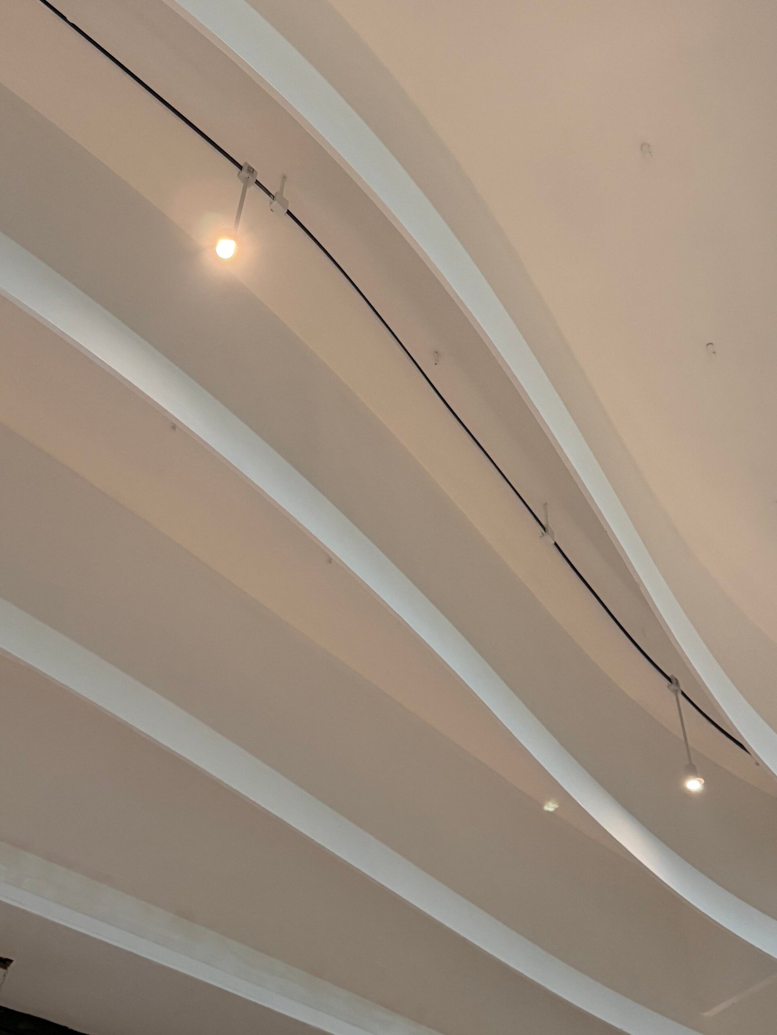
Project reference: curved ceiling geometry in a shopping-mall interior
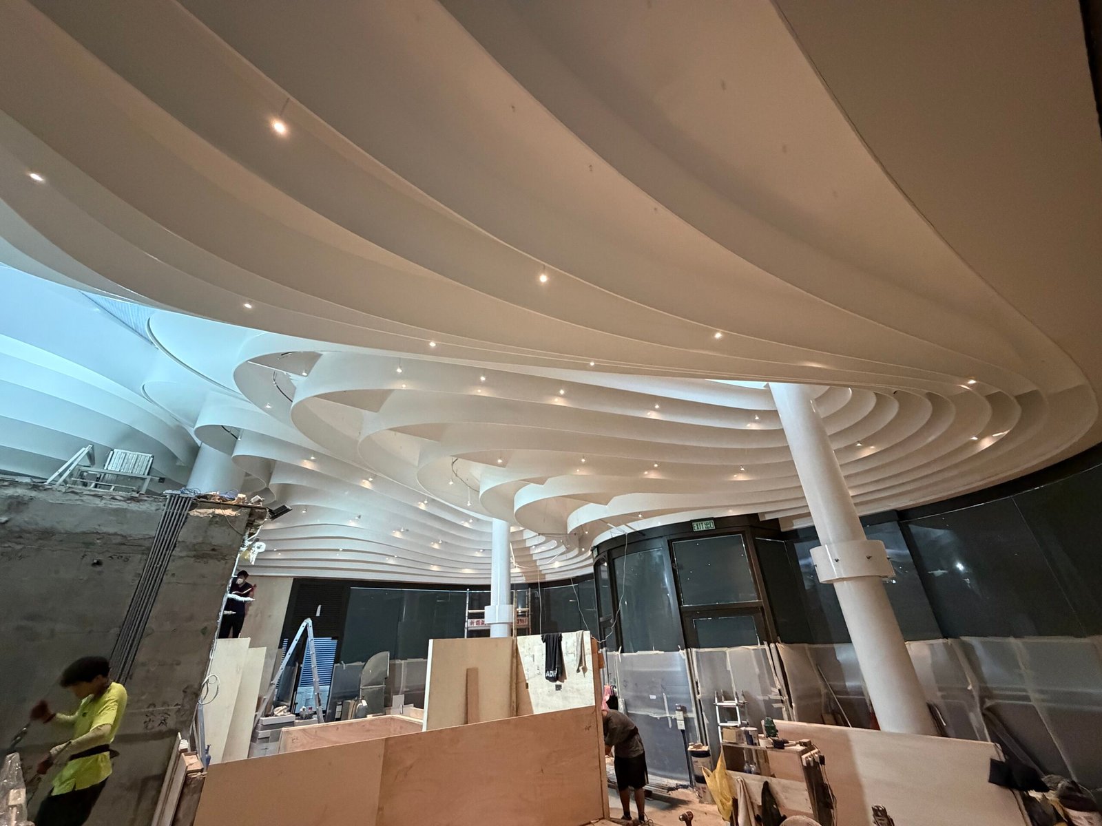
The three KLM-owned project photographs document a high commercial interior at construction stage. They show why the lighting route must be coordinated early: the curved white ceiling, structural zones, rail position, visual alignment and service access all influence the final result. No named client, location, final module schedule, curve radius, load calculation or completed performance claim is made here.
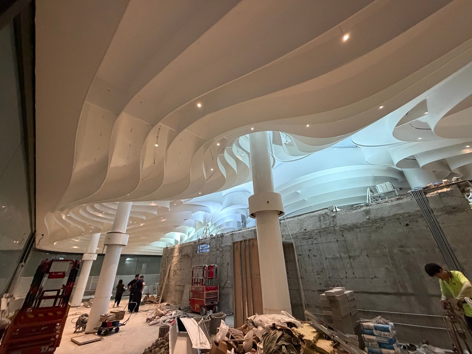
What can be tailored for a project
“Flexible” does not mean that every aspect is open-ended. For this type of system, design flexibility can be reviewed in three practical layers:
- Route: curved and changing architectural paths can be developed from the reflected ceiling plan and sections.
- Lighting composition: module types and locations can respond to displays, circulation, artwork, retail zones and feature areas.
- Project details: rail sections, junction locations, side-mounting conditions, finish coordination and power-entry locations can be checked against the drawing.
Any requested radius, special geometry, joint treatment, support spacing or non-standard part remains NEED CONFIRMATION until KLM reviews the final drawing and selected configuration.
Use side mounting to protect the ceiling concept
Side mounting can place the rail at a ceiling edge or vertical face rather than making it the dominant element on the main ceiling plane. This can help a lighting designer preserve the intended visual rhythm of a tall interior. It also makes the mounting substrate, fixing points, cable route and direction of each luminaire essential parts of the design review.
Specify the lighting task before selecting the module
| Design objective | What to define on the drawing | Why it matters |
|---|---|---|
| Accent a feature or display | Target object, aiming direction and mounting distance. | Determines the required module and beam effect. |
| Light a curved circulation route | Route, visual rhythm and control zone. | Prevents the track path from being decided after the ceiling is finished. |
| Support a retail or gallery zone | Fixture locations, glare constraints and access strategy. | Lets the selected modules respond to the actual task. |
| Integrate with a ceiling feature | Ceiling section, rail position and mounting face. | Confirms that the side-mounted detail works with the architecture. |
What to send KLM for a design review
- Dimensioned reflected ceiling plan, elevations and cross-sections.
- Curved route drawing, rail ends, junctions and proposed mounting faces.
- Target lighting effect and a module schedule for each area.
- Ceiling substrate, fixing constraints, installation height and access plan.
- 24V power/feed concept, driver/service location and control requirement.
- Quantity, destination, target date and any required project documentation.
FAQ
Can a curved side-mounted magnetic track be partially customized?
Project-specific route geometry, rail sections and mounting details can be reviewed from the drawing. KLM must confirm the selected configuration before quotation; do not assume an unrestricted radius or any geometry without review.
Is this system only for low ceilings?
No. The case reference here is a high-ceiling shopping-mall interior. The design decision is driven by the ceiling geometry, lighting task, mounting detail and access requirements.
Can I select any magnetic module for this rail?
No. Confirm the exact rail, adapter, luminaire, driver and control combination as one system.
How should a 24V layout be planned?
The feed points, driver capacity, load, cable route and control method depend on the final drawing and module schedule. KLM should check them before production.
Develop a Boya curved-track concept with KLM
Send KLM your ceiling plan and lighting concept for a project-specific review. See the Ultra-thin 24V Magnetic Track Lighting System and the wider magnetic lighting systems range for product context.
